


- 4,355 views, 2 today
- 149 downloads, 0 today

19
RedAppe
Mass storage won't be very massive. The RAM is already huge, so the mass storage can't be too much larger than the RAM, at least until I make the RAM more compact. In fact, the RAM is so large that I've decided to copy the RAM and use it as the mass storage (no extra building, either :]). This means the algorithms in the mass storage must be shorter than the actual executable version used in the RAM, so some sort of compiler or something must be used.
It should be noted that the mass storage will have 45 more useable bytes than the RAM, because the RAM acts as the distribution for inputs.
All this leaves is the execution circuitry. And the I/O, but weo ll ignore that for now.
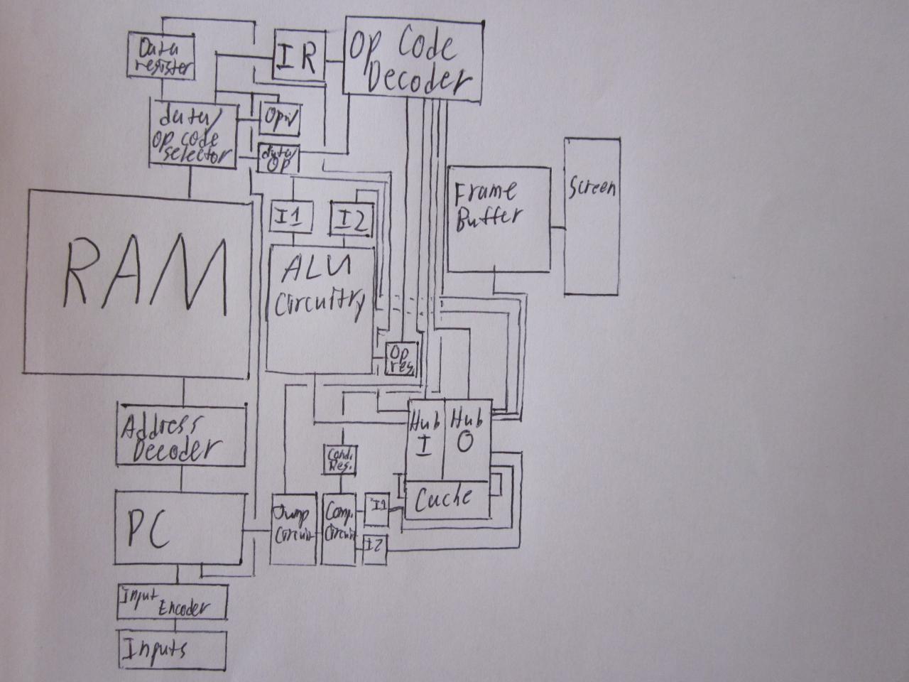
The MCedit schematic is from the old version of MCedit. I work in minecraft 1.1, then update the world.
I guess you can only upload 1 MCedit schematic at a time. I'll try to remember to rotate the schematics every now and then. Another schematic is in pt. 2. Requests for changes will always be accepted. What I've built so far:
-RAM Cell
-Comparison Circuit
-Hub Prototype
-Program Counter
-Input Panel
-Input Panel/Encoder attached to PC correctly
-Subtractor Circuit
-Multiplier Circuit
Currently: RAM cell. The other is the comparison circuit.
[Edit: I've discontinued work on this, because I decided to take a long break from computer engineering. Because of personal issues, I won't have as much time in the next few months, but I think I'll have enough time to work on neural nets.]
The RedAppe is a computer I recently designed, and still have to build. I have a semi-vague knowledge of how CPUs work, so some of the RedAppe is improvised. Io m sorry if some of what I write is redundant, but what I know isn't definite.
The MCedit schematic is just a part! Info down below, in additional notes.
Table of Contents:
1: Specs
2: The Cycle
3: The RAM
4: Mass Storage
5: The Hub
6: General-Purpose Registers
7: ALU
8: Jump Circuit
8: Input
9: Output
10: ISA
Some Specs and Other Info
Specs!
-256 bytes of RAM (2048 bits)
-2 level memory hierarchy
-45 user inputs
-8-bit instructions
-Dual-Fetch RAM (Basically, it combines two cells to create 16-bit cells, which is treated as two pieces of data, so RAM speed is doubled)
-Useful commands which allow o universal algorithms,o to reduce redundancy in memory (which I just found out are called procedural calls in real life)
-RISC (reduced instruction set computing) store/fetch architecture
The Cycle
The circuitry which fetches the next instruction uses instruction pipelining. This is what a cycle looks like:
1: PC sends data to the address decoder
2: Address decoder selects RAM cell
3: Once the previous two instructions finish executing, the RAMo s output is placed in a register. The pc is incremented by two, and the next instruction begins to be fetched.
4: The first half of the instruction executes. (Each RAM cell holds two data words.)
5: Once the first half executes, the second half executes.
6: Once the second half executes, the next data might be fetched. Once the RAMo s output has changed and is now stable, the cycle repeats. Although the data in two cells in a row might be exactly the same, the output will always change for at least a brief amount of time.
The RAM
The RAM is similar to DRAM, although the type in real life is impossible in minecraft. It has a 3-d grid of RAM cells which can be stored to and fetched from. However, two pieces of data are stored in one cell (I call it dual-fetch). This means instructions are effectively fetched twice as fast.
One nice thing about this is that it is extremely scalable. In parallel processors, scalability is an important factor. Ideally, a dual core processor would be twice as fast as a single core processor. However, that is virtually impossible to achieve. However, storing multiple pieces of data in each RAM cell is 95% scalable. It just takes larger input and output busses.
One thing to note is that this has already been invented. Both RevolutionalRedStone and I are working on large-scale RAMs, and we both came to the exact same conclusions.
Now to explain how it's similar to DRAM. Originally, I was going to use SRAM (static RAM), which is faster than DRAM (dynamic RAM), because the DRAM in real life is impossible in minecraft. All it uses is a single transistor and a single capacitator for each cell. Unfortunately, I tried to build the 256-byte SRAM, and couldn't. By removing a few components, I made the SRAM similar to DRAM and cut its volume in half, abouts. Whenever a cell is fetched from, the data is destroyed. This means that the output must be fed back into the input, so it refreshes the data whenever it is fetched. To store, select the address, and simply send data from a location other than the RAM. Additional circuitry is required to select which half of the cell is being stored to, because the RAM is dual-fetch. It just copies the data being stored to one half of the cell, and copies the other half of the original back to the other half of the cell.
There is more circuitry which causes the insta-repeaters to be fully utilized, but I'd rather let the handful of people who will want to know out how that works figure that out themselves. It would be way too ramble-y.
Mass Storage
Mass storage won't be very massive. The RAM is already huge, so the mass storage can't be too much larger than the RAM, at least until I make the RAM more compact. In fact, the RAM is so large that I've decided to copy the RAM and use it as the mass storage (no extra building, either :]). This means the algorithms in the mass storage must be shorter than the actual executable version used in the RAM, so some sort of compiler or something must be used.
It should be noted that the mass storage will have 45 more useable bytes than the RAM, because the RAM acts as the distribution for inputs.
All this leaves is the execution circuitry. And the I/O, but weo ll ignore that for now.
The Hub
The primary component in the execution circuitry is the hub, where most data transfer between its parts occurs. It consists of two multiplexors, one for the input, and one for the output (destination). The data selected by the first multiplexor is broadcast to the inputs of all of the other multiplexor, using a single vertical bus.
The hub is typically used indirectly, to transfer operands of instructions. The actual inputs and outputs depend on the instruction.
Besides making the computer more compact by using less bussing than simple locks (or whatever you want to call them, suppressors, etc.), it is very modular. It also means that most registers can be placed directly in front of the hub, with their data being wired directly through bussing in between the circuitry. Other circuitry can be placed directly attached to the registers.
A much smaller secondary hub is used for transferring second operands. It only has four inputs and two outputs, but doubles data transfer speed in most instructions.
General-Purpose Registers
In order to increase speed, several registers could be used for general storage. Because many would add 2 bits to the op code length, and the same purpose could be served by cache, I'm only going to use one GPR. Cache and one GPR together are just enough to hold data for operations with two operands.
ALU
The ALU is fairly simple. It has addition, subtraction, multiplication, increment, and no bit-wise operations. It has two input registers, and no output register. It would be unnecessary, because the operation to be done is held in a register, and the inputs are held in a register. General-purpose registers are used rather than an accumulator.
Jump Circuit
The jump circuit is primarily a comparison circuit, as well as circuitry to determine whether or not to jump. This takes into account the selected condition (held in a register) and whether or not the condition is supposed to be required.
Another part of the jump circuit is the circuitry used for the Jump (Algorithm) X command, and the circuitry for the Jump Back command. The Jump (Algorithm) X command is virtually the same as the normal jump command, but it stores the current location in the jump back register. If you already understand what I mean, youo re psychic. Sorry about that.
The Jump (Algorithm) X command is used when jumping to a universal algorithm, which is a commonly used algorithm such as displaying a binary number in decimal. Rather than copying the algorithm in every place it is used, a Jump (Algorithm) X command is used. This stores the current location in the jump back register (JBR). Every universal algorithm has a Jump Back command at the end, which causes the PC to jump to the address held in the JBR.
Of course, this could all be done by storing the previous address in RAM, cache, or a general purpose register. It improves the speed of the actual program algorithms, but it doesno t make a noticeable difference in speed, because it doesno t improve the speed of universal algorithms. The main purpose of this added circuitry is space efficiency. Reduce the space of each normal algorithm by a half, and much less RAM is used.
Instructions for universal algorithms are really only useful in large-scale RAM. In real computers, something similar to universal algorithms are used occasionally, but I dono t think real processors have instructions for universal algorithms. A processor with a large library of universal algorithms could use extremely little memory. If all useful basic functions were included in the library, it would only take three instructions for each basic function of the program.
You may be wondering how this is actually useful in real life. Sure, it can process a series of instructions held in RAM. But how does that allow a computer to do anything at all? This is where I/O comes in, aka input/output.
Input
The user input is based on external jump commands. Inputs will not do anything unless the processor has halted. When an input is activated, the PC is programmed, and the processor is started. It then runs the algorithm, which always ends with a HALT command. Each input has a fixed cell which it jumps to, but that cell always contains a jump command.
For example, if you typed o Oo in a word processing program, the input would select a RAM cell, which would then select another cell. An algorithm which writes the letter O on the screen, in the correct location, would then run.
The RedAppe has the inputs:
-A to Z
-0 to 9
-arrow keys
-enter
-end
-+,-,x
Thato s a total of 45 inputs, which requires 45 RAM cells, and many more for running a different algorithm for each input. Some programs do not use all the inputs, but it still brings up the chunk load issue. The RedAppe will have 128 10-bit cells; although I would rather it had many more. With the new block limit, maybe it will have more like 256 or 512 memory cells.
Output
The output is in the form of a frame buffer and a screen. The frame buffer contains a single frame, as well as logic gates to decode the data and display each pixel, each time the data changes. In order to increase speed of data manipulation, it can store rectangles, lines, and dots. This is done by storing four values: the y high, the y low, the x high, and the x low of the rectangle. Each o frame buffer cello is more like four RAM cells. FB cells are arranged like RAM cells, and each FB cell is accessed by an address. Only part of the output is used when the processor fetches data from the framebuffer. When outputting data to the screen, the entire output is used for the following operation:
Because the entire screen must be sequentially re-drawn each time a value is changed, a program counter type of thing is needed. The cycle:
1: Fetch the next piece of data.
2: Convert the data to pixels.
3: PC+1
4: Repeat until all data has been processed.
5: Once all data has been processed, output the new image to the screen.
The second step in re-drawing the screen is converting the data into pixels. Four decoders are used for this.
The first step in the displaying of the pixels is decoding each value into a physical output. What this means is that a 4-bit decoder would create 16 possible outputs. Once all decoders create their output: For the x and y values, the higher valueo s location sends a signal in the direction of the lower valueo s location, which stops at the lower valueo s location.
Once that has occurred for the x and y values, every location sends a signal in the direction of the other axis. Wherever both signals cross is sent to the re-drawn picture.
Another thing which is taken into account is whether or not the current FB cell has been suppressed. If it has, the entire process is skipped, and the PC is incremented.
Yeah!, that was really confusing! Luckily, you dono t really need to know how that works to know how the computer works. You just need to know that it uses four RAM cells for each shape (even if ito s just one pixel, unfortunately), and it can display squares, lines, and dots.
The screen will be 32 by 32 pixels.
Io m hoping that it will be able to store at least 64 shapes. Each cell is 20 bits (4 5-bit values), so the memory of the FB will be about 2/3 the size of the RAM.
Instruction Set Architecture
Bold and underlined numbers determine the type of operation. Underlined numbers are involved in the respective operation. Operand is what is being operated on.
Operands:
-Data Register
-Framebuffer (X)
-ALU Output
-Cache (X) Output
00000000 Compare
000000 Operand 1
000000 Operand 2
000000 Condition (GT, LT, EQ)
The condition is used if required during a jump command. Technically, only EQ and 1 other condition are necessary to create all conditions. By skipping what would happen if the desired condition isn't met, a jump can be used to act like an inverse condition of the one selected. However, this can create some redundancy in memory. Rather than having many things jump to one place with an algorithm, all must have a copy.
01000000 ALU
000000 Operand 1
000000 Operand 2
000000 Operation
It has +/-/x/increment 1st #. I'd like to avoid bit-wise operations, because I'm not sure how they would be useful with the operations it already has. I could make additional space for operations by making the addressing modes (deciding bits) more complex and less separate, so if you have any ideas, please tell me.
10000000 I/O
000000 First Memory (The 4 major Operands)
000000 Second Memory (RAM, Cache, Framebuffer, Mass Storage)
000000 I/O Decider (Which group acts as the data, which as the destination.)
000000 HALT
The listed memory stuffs are what is being inputted or where the data is being output to.
I/O is actually more parallel than the parallel instruction, but it wono t be in the RedAppe II. Around 8 additional second memories will be added.
When RAM is being fetched from, the MAR is used to select the address rather than the PC, which is important to be able to move instructions, as well as integers.
Because the memories can both be used as input or output, it is possible to use any memory for general storage. I just thought of this, to be frank, so I guess I have more work to do. Maybe the framebuffer isno t necessary. Instead, everything could be stored in RAM, with other memory which already existed to tell which is to be rendered on the screen. Hmmmmo ¦ Nah. It would take a larger address, which would be really annoying speed-wise.
Having HALT as part of I/O is strange, but it was necessary for an 8-bit op code.
11000000 Parallel
000000 Integer/Destination, Jump Unconditionally, Jump Conditionally, Jump Algorithm Unconditionally, Jump Algorithm Conditionally, Jump Back, Fetch Integer from
000000 Suppress Selected Framebuffer Cell, Unsuppress Selected Framebuffer Cell
I love the parallel command.
The integer/destination is the method for quickly fetching data. Rather than cutting a command by containing the data within a command, a command is cut by pre-determining the output. The jump commands are similar to a program counter integer, but some require a condition to be met, and some cause the current location to be sent to the jump back register. If the condition is not met (if required), the next instruction is skipped (which wouldo ve been used as a PC integer).
The Jump Back command causes the jump back registero s data to be sent to the program counter. In a way, it is another type of jump command.
The suppress/unsuppress selected framebuffer cell determines whether or not the cello s data will be rendered on the screen.
Because Planet Minecraft articles are limited in length, Io ve split this into two parts. If youo re reading this, thanks! :] In the next part, I'll give some stupidly fine details, some plans for the future, and some algorithms.
Additional Notes
The MCedit schematic is from the old version of MCedit. I work in minecraft 1.1, then update the world.
I guess you can only upload 1 MCedit schematic at a time. I'll try to remember to rotate the schematics every now and then. Another schematic is in pt. 2. Requests for changes will always be accepted. What I've built so far:
-RAM Cell
-Comparison Circuit
-Hub Prototype
-Program Counter
-Input Panel
-Input Panel/Encoder attached to PC correctly
-Subtractor Circuit
-Multiplier Circuit
Currently: RAM cell. The other is the comparison circuit.
| Credit | RevolutionalRedStone, for telling me some technical terms and keeping me building. Ninjalux is helping to build things, and to make them faster. I'll be using the alternative full adder on the wiki by Howlingmonkey. Couldn't contact and ask for permission |
| Progress | 50% complete |
| Tags |
18 Update Logs
Update #18 : by Monkeysaucer 06/19/2012 1:12:00 pmJun 19th, 2012
I've decided to use insta-repeaters, because I found out transistors in real life have 150 million times the delay as a piece of wire the same length (30 nanometers.) I rebuilt the RAM cell so it is more similar to DRAM, rather than SRAM, and it's now about half the volume. It uses insta-repeaters, but is still dual-fetch, because the actual circuitry is slow.
LOAD MORE LOGS
tools/tracking
624696
2
redappe-computer


 dreamCritting
 Sophisticated_Trashcan
 Arkaliasus
 ScotsMiser
 SteamMallard07
 LongerBlade
 pocapka
 person_02
 Octogamer
 sjen_2001

 XXHIKKIXX
 SeaJay Plays
 Insidious_Purr
 Meat_Mallet
Create an account or sign in to comment.
This project grew more and more complex, to the point of being absolutely impossible to build. When designing redstone devices, elegance/simplicity are more important than efficiency. Try to find the simplest ways to do the most useful things.
DIAMOND FUR YU BECUZ DIS DEZURVZ EET