• 4/8/12 6:58 am
- 609 views • 0 today
- save_alt 13 downloads
- Progress
- 100% complete

1
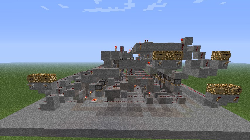
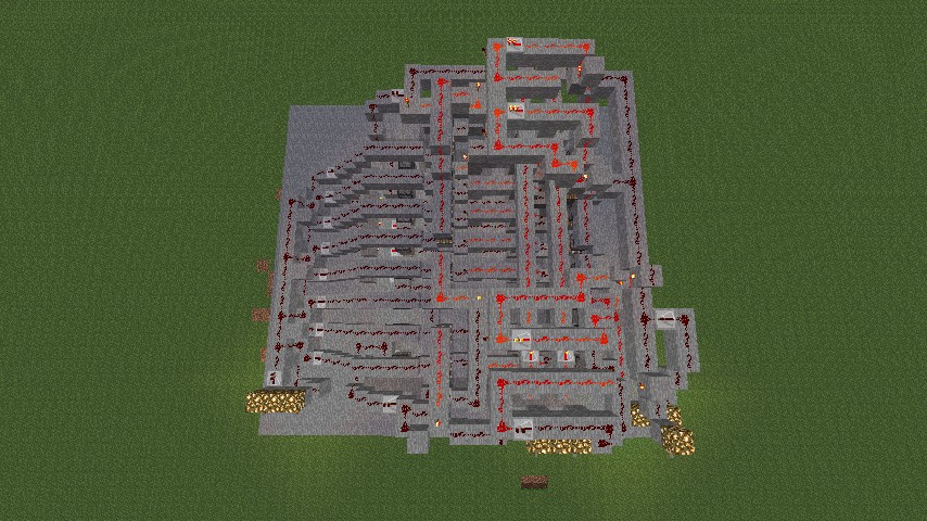
8 BIT (4x2 BIT CLUSTER) RAM
INTRODUCTION
This RAM memory is the first memory I, Medicijnman, built and actually worked. Its design is completely created by myself. Further on this post I will call this "RAM".
Dimensions : 23x26x12
SUMMARY
Introduction
Specs
Redstone components
How to use
Example
SPECS
The RAM has the following features:
- 4 clusters of 2 bits
- write data to 1 cluster
- read data from 1 cluster
REDSTONE COMPONENTS
The RAM has the following logical ports and redstone components:
- 8 edge triggered D flip flops (2 flip flops for each cluster)
- 2 to 4 decoder (cluster decoder)
- 16 piston check systems
- NOT and OR logic gates
HOW TO USE
The RAM has 2 bits for each cluster, thus you can read and write at most and at least 2 bits per execution. A mini/cryptic description is above every lever.
See also the lever descriptions and its meaning:
DATA bit 1
this bit is the most significant bit that you can write to a cluster, thus its value is 2.
DATA bit 0
this bit is the least significant bit that you can write to a cluster, thus its value is 1.
CLUSTER bit 1
this bit is the most significant bit that tells the RAM to which cluster you want to write data to or which cluster you want to read data from, thus its value is 2.
CLUSTER bit 0
this bit is the least significant bit that tells the RAM to which cluster you want to write data to or which cluster you want to read data from, thus its value is 1.
WRITE data bits to cluster
When down, the RAM writes data bits to a cluster. When not down, the output bits show the selected cluster's data.
OUTPUT bit 1
This bit is the most significant bit that shows the selected cluster's data bit 1, thus its value is 2.
OUTPUT bit 0
This bit is the least significant bit that shows the selected cluster's data bit 0, thus its value is 1.
If you still don't get it, take a look at EXAMPLE.
EXAMPLE
Here are two examples to write and read a cluster's data:
1) WRITE DATA TO A CLUSTER
Lets say we want to write 3 (11) to cluster 2 (10). The levers are in the following states:
DATA bit 1, down
DATA bit 0, down
CLUSTER bit 1, down
CLUSTER bit 0, up
WRITE, up
The output should be:
OUTPUT bit 1, selected cluster bit 1
OUTPUT bit 0, selected cluster bit 0
If we then pull WRITE down, the RAM executes our instruction.
2) READ DATA FROM A CLUSTER
Lets say we want to read cluster 1 (01). The levers are in the following states:
DATA bit 1, up
DATA bit 0, up
CLUSTER bit 1, up
CLUSTER bit 0, down
WRITE, up
The output should be:
OUTPUT bit 1, selected cluster bit 1
OUTPUT bit 0, selected cluster bit 0
Please note: when WRITE is off/up the data bits don't make sense!
More like this

 whitefyre1
 ecolortest
 BradleyM
 MrRedstoneFTW
![(First Ever?) Repeater RAM [8 Bit] Minecraft Map & Project](https://static.planetminecraft.com/files/resource_media/screenshot/1318/Panorama-View_5376749_thumb.jpg)
 XenoTech
755639
2

![Block Destroyer - VERY FAST! [1.25] Minecraft Map & Project](https://static.planetminecraft.com/files/resource_media/screenshot/1218/2012-05-03_205536_2154066_thumb.jpg)


 Viriaziajnio
![The Fallen Angel - Alexandre Cabanel [Schematic] Minecraft Map & Project](https://static.planetminecraft.com/files/image/minecraft/project/2026/021/19990791_s.jpg)
 VintagePhil
![[FREE] 1-528KP-40 (Nadezhin's point) | 1-528КП-40 (Точка Надёжина) Minecraft Map & Project](https://static.planetminecraft.com/files/image/minecraft/project/2026/584/19983347-huge_s.jpg)
 artificialis
 Carlostc2003
 GuardianYT
Have something to say?