



• 5/19/13 1:47 pm
- 808 views • 0 today
- save_alt 17 downloads
- Progress
- 100% complete
Added CreditXenoTech, AdmBot, MCMedicijnman


10
Arithmetic Logical Unit [8 bit]
Number of instructions: 4* (OR, ADD, AND, and NOT)
Number size: 8 bits
Download: schematic
*)It is possible to use another instruction: SUBtract two numbers. Thererfore, you have to do two things: first, you need to enable the carry in from the first alu slice (obsidian block on the left). Second, you need to invert the input from one of the numbers.
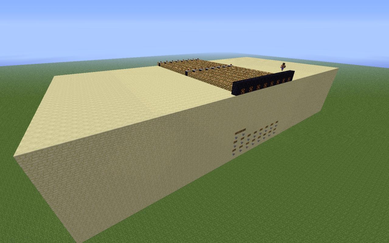
We adapted this design from a book called "Computer Organization" by Andrew S. Tanenbaum. This ALU uses two 8 bit unsigned numbers. The two lowest rows of levers on the control panel represent the first and second number. The upper 2 levers determine what opcode to perform on those numbers. We placed some redstone lamps on the output and on the roof.
When adding two numbers, the carry out (overflow, whatever) is on the right side of the ALU.
NOTE: we haven't had tested all possible combinations, some operations therefore may result in incorrect answers. If you are experiencing any problems, please inform us.
Quick Overview
Number of instructions: 4* (OR, ADD, AND, and NOT)
Number size: 8 bits
Download: schematic
*)It is possible to use another instruction: SUBtract two numbers. Thererfore, you have to do two things: first, you need to enable the carry in from the first alu slice (obsidian block on the left). Second, you need to invert the input from one of the numbers.
Overview
We adapted this design from a book called "Computer Organization" by Andrew S. Tanenbaum. This ALU uses two 8 bit unsigned numbers. The two lowest rows of levers on the control panel represent the first and second number. The upper 2 levers determine what opcode to perform on those numbers. We placed some redstone lamps on the output and on the roof.
When adding two numbers, the carry out (overflow, whatever) is on the right side of the ALU.
NOTE: we haven't had tested all possible combinations, some operations therefore may result in incorrect answers. If you are experiencing any problems, please inform us.
Known issues / Stuff to do
- Testing SUBtract routine
More like this


 ULTRATHIN 160 bit arithmetic logic unit (ALU)Redstone Device Map
 Reaper559666
•12/19/11 9:09
914 38 4x 38
Reaper559666
•12/19/11 9:09
914 38 4x 38
![(First Ever?) Repeater RAM [8 Bit] Minecraft Map & Project](https://static.planetminecraft.com/files/resource_media/screenshot/1318/Panorama-View_5376749_thumb.jpg)
 Kernul
 Undertuck
2154710
2
![[STACKABLE][COMPACT][FAST] 8x8 display Minecraft Map & Project](https://static.planetminecraft.com/files/resource_media/screenshot/1331/panorama_6076019_thumb.jpg)
![[STACKABLE][COMPACT][FAST] Hexadecimal Counter With Display Minecraft Map & Project](https://static.planetminecraft.com/files/resource_media/screenshot/1326/Panorama_5799439_thumb.jpg)
![[FAST] Mono-directional Read and Write Tape (46 bytes) Minecraft Map & Project](https://static.planetminecraft.com/files/resource_media/screenshot/1322/Panorama_5570844_thumb.jpg)
![Arithmetic Logical Unit [8 bit] Minecraft Map & Project](https://static.planetminecraft.com/files/resource_media/screenshot/1320/Panorama-View-1_5498209_thumb.jpg)




 ASAKA828

 vaporr


Have something to say?
I noticed your using unsigned numbers; but the subtraction you put-forward sounds like the 2-s compliment method...
The twos compliment method works; but it doesn't offer you the full range of positive integers ( and it also doesn't reverse over-flow when going into negative ) to subtract without the issues i mentioned; invert one of the inputs ( the one being used as the subtrahend ) and then invert the whole output ( ignore the final carryout bit ) and your result should be correct.
Also i like the operations you selected; except NOT, surely it ought to be NOR ( since your ALU has 2-inputs and since it replaces Not anyway if you ignore the second input )
Awesome work XenoTech; next you should hookup a memory bank to act as input and output for this device : )
The subtraction routine is indeed the 2-s compliment method, but I haven't had tested the subtraction routine though. I'm not quite sure, but I thought that the carry out is inverted when the ALU performs the subtraction routine. I am going to update the description when I have tested the redstone device more thoroughly.
Because this design is an exact copy from a book called "Computer Organization", I had not had the intention to alter its operations. A NOR operation would indeed be a better choice.
I also have an amount of RAM redstone devices (16 byte till 256 byte capacity, I don't know whether you've seen them already), but do you think it would be usefull to hook up one of them to this ALU? The larger RAM devices are very slow and not that efficient I guess.
Currently, it is not as good as I wanted it to be (it's still very huge, slow, and some wires are not synchronized), but I'm still satisfied that this is our first working 8 bit ALU :).
There is of-coarse no-way to actually represent negative numbers in binary so instead we use one of two tricks...
We can use a new encoding scheme ( such as the standard two's complement representation ) it works by taking half of a binary values range and pushing it below zero.
( so an 8-bit number would change ranges from 0 - 255 to -128 - 127 )
We can also subtract without using a new encoding scheme ( i came up with this method after learning how to use two's complement representation ) This trick works by intentionally overflowing the adder; You see i realized that in binary; subtracting value A by value B is exactly equivalent to adding the maximum representable binary number minus value B. ( so if you want to subtract two from an eight-bit binary number then add 254 to it; after overflow it will have gone all the way around the max representable back to zero and will have ended-up two lower than when it started )
to-do the first subtraction method, invert the second input, add one to it ( by enabling the carry-in ) and then Add.
to-do the second method, invert the second input, Add, and then invert the output.
I remember reading structured computer organization at uni; he really covers a lot, i think there was even a small project on tri-state bits wasn't there?
I have seen your awesome looking memory; i think it's a great idea to hook some up !
Again really nice work on this project : )
The subtraction routine is just a suggestion to users that may want to subtract two numbers, but they need to process the input and/or output wires in order to use this routine (using one of your methods mentioned in your post). I think I will change the description to make it clear that the subtraction routine isn't implemented in the machine, but that it's possible to use that routine.
Tri-state bits were mentioned in that book, i.e. 1, 0, and floating, but in MC I think floating also means 0 (I don't know if it's even possible in MC to use or transfer more than two different states?).
Currently, I don't know how I am going to hook up some of the RAM devices, because just connecting some wires won't do it :P. In order to do something useful with the ALU and RAM device, what components do I need to create? I think you need:
- A control device (something that receives input from RAM and sends output from the ALU back to RAM), maybe with a memory address register to remember the locations in RAM.
- A data bus (data from RAM to the ALU and from the ALU back to RAM)
- One or more buffers (to prevent data loss)
- Clock pulse generator (to make sure every component operates in sync)
I think the control device will be the most difficult component to design. In order to tell the control device what to do I think I also need to create an instruction set for the control device, but I really don't know how I am going to do that :P